| The
problem with on-board BEC's
The on-board BEC's on ESC's (Electronic Speed Controllers) often have a hard time
working from 3-cell LiPo packs. They have to regulate power from 11.1V down to 5V. A
difference of 6V. I've had more than one incident because the BEC on a ESC just couldn't
cope and shut down completely, resulting in total loss of control of the model.
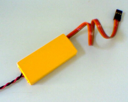
Then I found this nifty BEC unit on the web.
The design is modular, i.e. it can be built as big or small as you require, by adding as
many 1A modules as you want. An added safety feature is that it has built-in redundancy.
It can also handle input from 8 - 16 NiCd cells (9.6 - 16.8V) or 3 - 4 LiPo's.
Why external BEC's is a good idea
The logic behind using an external BEC unit is quite simple. Since heat is a
by-product of a voltage regulator, it has to be dissipated in some way - usually sharing a
common heat sink with a lot of MOSFET's on the ESC.
So, by not adding this heat burden to an
already hard working ESC, but rather using a dedicated heat sink (on a separate BEC unit),
it's not only kind to the ESC (by relieving it from regulating power for the receiver and
servos), but it also ensures that the BEC is not directly affected by the heat from the
ESC. The result is a much more reliable setup, in my opinion.
Information and construction details can be
found in the original post
by Suzanne, the designer (home page: http://333100023998.bei.t-online.de/
)
Although, the design is described there in
detail, I found this website to be more helpful:
http://www.dream-models.com/eco/electrics-bec1.html
|